How to change an Extra Low Voltage (ELV) Downlight transformer
From your Warrington Electrician – Capper Shaw Electrical Ltd.
1) Drop light fitting from ceiling by pulling down from edges using fingertips. You should feel some resistance as the Downlight is held up via spring loaded arms attached to the side (fig1)
Fig (1)
![]()
2) Ensure power is isolated by following reliable isolation procedures and using appropriate test equipment. (See Isolation procedures Fig2 and fig3 at the end of this article)
3) Locate junction box (fig 1) and remove lid, loosen line and neutral terminals and remove transformer cores. The light and transformer should now be detached from the junction box.
4) Open electrical terminal on light fitting and loosen the connector screws. Remove the two cores from the transformer. The transformer can now be disposed of according to manufacturer’s instructions (NB – you may need the details of this transformer to purchase the correct replacement transformer).
5) Attach the secondary winding (12v side) cores of the new transformer to the light fitting terminal. These will be 2x single cables both of the same colour, it doesn’t matter which core goes to which terminal. They are Line/Line.
6) Ensure all cores (both from transformer and to lap holder) are well attached under the screws by giving them a slight pull. Close the lid on the light fitting terminal.
7) Your transformer should now be attached to the downlight.
8) Now, at the junction box protruding from the ceiling, attach the brown (Line) conductor of the transformer, to the brown (Line) terminal in the junction box, Check all brown cores are firmly crimped by terminal screw by gently pulling on each core.
9) Repeat step 8 with blue cores from the transformer and and the in and out blue (neutral) cores. Put lid on junction box.
10) Feed junction box and transformer back through the hole for light. Squeeze back two spring arms and push back through downlight hole. Shift downlight into position that best achieves flush fitting and covers any unpainted/unplastered areas.
11) Energise installation and check operation.
Fig 2 – Isolation procedure
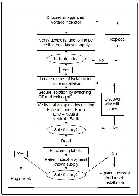
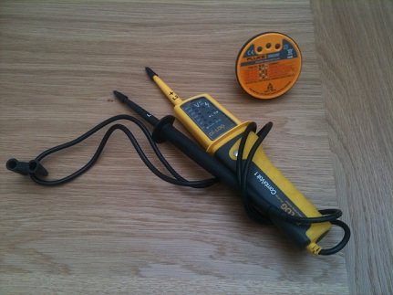
Fig 3 – Voltage indicator